Zonal control reduces latency, improves fail-safety, and supports future vehicle updates through software-defined control.
James Colby, Littelfuse, explores how the evolution of electric and intelligent vehicles has changed the way engineers think about power distribution and electronic control, with modern cars featuring hundreds of interconnected electronic control units (ECUs) that control everything from powertrain management to occupant safety and advanced driver-assistance systems (ADAS)
To manage this complexity, automotive electronics have gone through three stages:
- Distributed Architecture- each ECU connects to a central controller.
- Domain Architecture- functional grouping decreases bus load but increases wiring complexity.
- Zonal Architecture- ECUs are grouped by physical location and managed by a Zonal Control Unit (ZCU), responsible for each area of the vehicle.
This zonal shift strengthens local control, simplifies harnesses, decreases weight, and enables scalable, modular design. Zonal control also reduces latency, improves fail-safety, and supports future vehicle updates through software-defined control.
Enhancing EV efficiency and reliability
In EVs, the ZCU serves as the command centre for its region, grouping data, managing distributed ECUs, and maintaining reliable communication with other zones using high-speed Ethernet or CAN-FD.
The zonal approach can improve energy efficiency and safety due to optimising battery management, power conversion, and load control under dynamic conditions. However, this can introduce electrical risks, including transient surges, electrostatic discharge (ESD), and overcurrent events. As a result, protection strategies are critical to preserving performance and meeting automotive reliability standards.
Protecting the ZCU
Due to serving as the electrical and communication hub for each vehicle section, the ZCU must withstand faults, transients, and demanding operating conditions.
Faults in the supply or load circuitry can cause overcurrent conditions. To protect the power supply, use:
- Fast-acting fuses or polymer PTC resettable fuses to isolate faults and prevent damage.
- Transient Voltage Suppression (TVS) diodes or metal oxide varistors (MOVs) to absorb high-voltage load dumps.
Communication buses such as CAN, LIN, and Ethernet need to maintain integrity under ESD and surge events, to protect communication and control lines:
- Apply low-capacitance ESD diodes or polymer suppressors to protect signal lines without degrading transmission.
- Choose protection devices with response times under one ns and low leakage to prevent interface with data flow and decrease power consumption.
All components should meet automotive-grade temperature, vibration, and humidity requirements. Qualified fuses, MOVs, and ESD suppressors ensure long-term reliability even under challenging thermal cycling or voltage stress. Selected components should meet AEC qualification standards.
Safeguarding the onboard battery charger
The Onboard Battery Charger (OBC) converts AC input to the DC voltage that charges the vehicle's battery pack, operating between 400V and 800V. As higher-power chargers become standard, ensuring protection from grid and vehicle-induced transients becomes vital.
For input and surge protection, consider using:
- A high-interrupting-current fuse on the AC input to protect against overloads.
- MOVs near the AC input terminals to absorb surges caused by lightning or grid switching. Add MOVs between phase-phase and phase-neutral lines for three-phase systems.
- Combine MOVs with thyristors to clamp at lower voltages and at faster speeds, decreasing the peak voltage downstream.
- Gas Discharge Tubes (GDTs) for additional isolation between hot and ground lines to increase safety against lightning-induced transients.
- Residual Current Monitors (RCMs) to detect insulation leakage or AC/DC fault current as low as 6mA or 10mA AC.
Rectifier and Power Factor Correction:
- Use high-current thyristors and IGBTs that can handle inrush and transient conditions.
- Integrate gate drivers with strong latch-up immunity, accelerated switching, and ESD robustness up to 30kV.
DC/DC conversion and output stage:
- Use TVS diodes between collector and gate to stabilise IGBTs for voltage step-up/down circuits.
- Use MOVs or TVS diodes to protect the output voltage from transient spikes.
- To guard against short circuits or battery wiring faults, apply fuses in the DC path.
- Add ESD diodes to communication lines linking the OBC and ZCU to prevent data corruption.
Applying these protections allows the OBC to safely manage rapid charging cycles and grid disturbances while ensuring long-term performance.
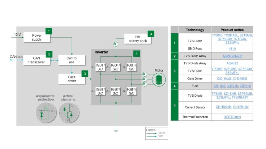
Protecting the traction motor inverter
The Traction Motor Inverter converts DC from the battery into three-phase AC for a propulsion motor. This subsystem endures high current and voltage stress, so it requires accurate control and protection for power semiconductors.
Power supply and gate driver protection:
- Use fuses and TVS diodes to protect the DC bus from voltage spikes.
- Protect the CAN transceiver with ESD diode arrays, as recommended for ZCU CANN/CAN-FD circuits.
- To prevent electrostatic or switching-induced damage, protect the gate driver ICs using ESD arrays.
Semiconductor protection:
- For SiC MOSFETS, a TVS between gate and source can mitigate fast transients.
- Use collector-to-gate TVS diodes to clamp high-voltage transients for IGBTs.
- Integrate thermal protectors to interrupt the current when over-temperature conditions arise.
Current monitoring and diagnostics:
- Utilise hall-effect current sensors for isolated motor load current monitoring, enabling real-time detection of load anomalies without adding series resistance or power loss.
Long-term reliability
As the automotive industry moves toward software-defined, electrified vehicles, the transition to zonal architectures can provide benefits in scalability, safety, and cost. This distributed intelligence, however, depends on robust electrical protection throughout the powertrain and control system.
To achieve this, implement a layered protection using fuses, MOVs, TVS diodes, and ESD suppressors, select automotive-grade components rated for challenging environmental stress, integrate protection early in the design process to simplify validation and avoid downstream re-engineering, and collaborate with component experts who can advise on pre-compliance testing and automotive safety standards, decreasing certification delays.
Zonal control is changing the way vehicle electronics are organised, creating more responsive, resilient, and efficient architectures. By utilising appropriate overcurrent, overvoltage, and ESD protection strategies, engineers can ensure each zone remains robust under real-world operating conditions.